HOW TO CLASSIFY NON-CONTACT THERMOMETERS?
- Broadband radiation thermometers/pyrometers
- Narrow band radiation thermometers/pyrometers
- Ratio radiation thermometers/ pyrometers
- Optical pyrometers
- Fiber optic radiation thermometers/pyrometers
These classifications are not rigid. For example, optical pyrometers can be considered a subset of narrow band devices. Fiber optic radiation thermometers, to be discussed in detail in another section, can be classified as wide band, narrow band, or ratio devices. Likewise, infrared radiation thermometers can be considered subsets of several of these classes. Historically a radiation non-contact thermometer consisted of an optical system to collect the energy emitted by the target; a detector to convert this energy to an electrical signal; an emittivity adjustment to match the thermometer calibration to the specific emitting characteristics of the target, and an ambient temperature compensation circuit, to ensure that temperature variations inside the thermometer due to ambient conditions did not affect accuracy.
The modern infrared thermometer is still based on this concept. However the technology has become more sophisticated to widen the scope of the applications that can be handled. For example, the number of available IR detectors has greatly increased, and, thanks to selective filtering capabilities, these detectors can more efficiently be matched to specific applications, improving measurement performance.
Non-contact temperature measurement is the preferred technique for small, moving, or inaccessible objects; dynamic processes that require fast response; and temperatures 1000°C (1832°F). To select the best noncontact temperature measurement device for a particular application, it is essential to understand the basics of temperature measurement technology, temperature measurement parameters, and the features offered by the various measurement systems currently available.
Broadband Radiation temperature sensors
Broadband non-contact thermometers typically are the simplest devices, cost the least, and can have a response from 0.3 microns wavelength to an upper limit of 2.5 to 20 microns. The low and high cut-offs of the broadband thermometer are a function of the specific optical system being used. They are termed broadband because they measure a significant fraction of the thermal radiation emitted by the object, in the temperature ranges of normal use.
Broadband infrared thermometers are dependent on the total emittance of the surface being measured. Figure 3-2 shows the error in reading for various emissivities and temperatures when a broadband device is calibrated for a blackbody. An emissivity control allows the user to compensate for these errors, so long as the emittance does not change.
The path to the target must be unobstructed. Water vapor, dust, smoke, steam and radiation absorptive gases present in the atmosphere can attenuate emitted radiation from the target and cause the thermometer to read low.
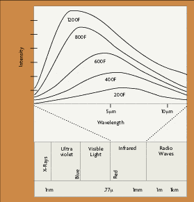 Image Caption Title
The optical system must be kept clean, and the sighting window protected against any corrosives in the environment.
Standard ranges include 32 to 1832°F (0 to 1000°C), and 932 to 1652°F (500 to 900°C). Typical accuracy is 0.5 to 1% full scale.
Narrow Band Radiation
As the name indicates, narrow band radiation IR thermometers operate over a narrow range of wavelengths. Narrow band devices can also be referred to as single color pyrometers. The specific detector used determines the spectral response of the particular device. For example, a non-contact thermometer using a silicon cell detector will have a response that peaks at approximately 0.9 microns, with the upper limit of usefulness being about 1.1 microns. Such a device is useful for measuring temperatures above 1102°F (600°C). Narrow band thermometers routinely have a spectral response of less than 1 micron.
Narrow band non contact thermometers use filters to restrict response to a selected wavelength. Probably the most important advance in radiation thermometry has been the introduction of selective filtering of the incoming radiation, which allows an instrument to be matched to a particular application to achieve higher measurement accuracy. This was made possible by the availability of more sensitive detectors and advances in signal amplifiers.
Common examples of selective spectral responses are 8 to 14 microns, which avoids interference from atmospheric moisture over long paths; 7.9 microns, used for the measurement of some thin film plastics; 5 microns, used for the measurement of glass surfaces; and 3.86 microns, which avoids interference from carbon dioxide and water vapor in flames and combustion gases.
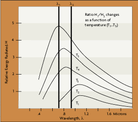 Image Caption Title
Standard temperature ranges vary from one manufacturer to the next, but some examples include: -36 to 1112°F (-37.78 to 600°C), 32 to 1832°F (0 to 1000°C), 1112 to 5432°F (600 to 3000°C) and 932 to 3632°F (500 to 2000°C). Typical accuracy is 0.25% to 2% of full scale.
Ratio Radiation IR devices
Also called two-color infrared non contact thermometers, these devices measure the radiated energy of an object between two narrow wavelength bands, and calculates the ratio of the two energies, which is a function of the temperature of the object. Originally, these were called two color pyrometers, because the two wavelengths corresponded to different colors in the visible spectrum (for example, red and green). Many people still use the term two-color pyrometers today, broadening the term to include wavelengths in the infrared.
The non-contact thermometers are dependent only on the ratio of the two energies measured, and not their absolute values as shown in Figure 3-4. Any parameter, such as target size, which affects the amount of energy in each band by an equal percentage, has no effect on the temperature indication. This makes a ratio thermometer inherently more accurate. (However, some accuracy is lost when you're measuring small differences in large signals).
The ratio technique may eliminate, or reduce, errors in temperature measurement caused by changes in emissivity, surface finish, and energy absorbing materials, such as water vapor, between the thermometer and the target. These dynamic changes must be seen identically by the detector at the two wavelengths being used.
Emissivity of all materials does not change equally at different wavelengths. Materials for which emissivity does change equally at different wavelengths are called gray bodies. Materials for which this is not true are called non-gray bodies. In addition, not all forms of sight path obstruction attenuate the ratio wavelengths equally. For example, if there are particles in the sight path that have the same size as one of the wavelengths, the ratio can become unbalanced.
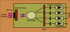 Image Caption Title
Two color non contact thermometers should be seriously considered for applications where accuracy, and not just repeatability, is critical, or if the target object is undergoing a physical or chemical change.
Ratio thermometers cover wide temperature ranges. Typical commercially available ranges are 1652 to 5432* F (900 to 3000°C) and 120 to 6692°F (50 to 3700°C). Typical accuracy is 0.5% of reading on narrow spans, to 2% of full scale.
Optical Pyrometers
Optical pyrometers measure the radiation from the target in a narrow band of wavelengths of the thermal spectrum. The oldest devices use the principle of optical brightness in the visible red spectrum around 0.65 microns. These instruments are also called single color pyrometers. Optical pyrometers are now available for measuring without contact energy wavelengths that extend into the infrared region. The term single color pyrometers has been broadened by some authors to include narrow band radiation thermometers as well.
 Image Caption Title
Some optical designs are manually operated as shown in Figure 3-8. The operator sights the pyrometer on target. At the same time he/she can see the image of an internal lamp filament in the eyepiece. In one design, the operator adjusts the power to the filament, changing its color, until it matches the color of the target. The temperature of the target is measured based upon power being used by the internal filament. Another design maintains a constant current to the filament and changes the brightness of the target by means of a rotatable energy-absorbing optical wedge. The object temperature is related to the amount of energy absorbed by the wedge, which is a function of its annular position.
Automatic optical pyrometers, sensitized to measure in the infrared region, also are available. These instruments use an electrical radiation detector, rather than the human eye. This device operates by comparing the amount of radiation emitted by the target with that emitted by an internally controlled reference source. The instrument output is proportional to the difference in radiation between the target and the reference.
Fiber Optic Radiation
Although not strictly a class unto themselves, these devices use a light guide, such as a flexible transparent fiber, to direct radiation to the detector, and are covered in more detail in the chapter beginning on p. 43. The spectral response of these fibers extends to about 2 microns, and can be useful in measuring object temperatures to as low as 210°F (100°C). Obviously, these devices are particularly useful when it is difficult or impossible to obtain a clear sighting path to the target, as in a pressure chamber.
Defining the terms
Gereral glossary for Non Contact thermometers
IR Radiation. Infrared is that portion of the electromagnetic spectrum beyond the visible (blue to red, 0.4-0.75 µm) response of the human eye. IR wavelengths extend from 0.75 µm to 1000 µm, where the shortest microwaves (radar) begin. Because IR radiation is predominantly generated by heat, it is called thermal radiation.
For non contact thermometers, only portions of the IR spectrum are important. The spectrum is frequently divided into “atmospheric windows” that provide maximum loss-free transmission through water vapor in air: 0.7-1.3 µm; 1.4-1.8 µm; 2.0-2.5 µm; 3.2-4.3 µm; 4.8-5.3 µm; 8-14 µm
Emissivity. This quality defines the fraction of radiation emitted by an object as compared to that emitted by a perfect radiator (blackbody) at the same temperature. Emissivity is determined in part by the type of material and its surface condition, and may vary from close to zero (for a highly reflective mirror) to almost 1 (for a blackbody simulator). Emissivity is used to calculate the true temperature of an object from the measured brightness or spectral radiance. Because an object’s emissivity may also vary with wavelength, a radiation thermometer with spectral response matching regions of high emissivity should be selected for a specific application. Emissivity values are listed in the literature for a variety of materials and spectral bands, or these values can be determined empirically.
Brightness/Single-Color Pyrometer. These devices measure and evaluate the intensity, or brightness, of the intercepted thermal radiation. Intensity, or, more generally, spectral radiance, is measured in a narrow wavelength band of the thermal spectrum. Band selection is dictated by the temperature range and the type of material to be measured.
Ratio/Two-Color Pyrometer.This non contact thermometer measures temperatures on the basis of two (or more) discrete wavelengths. The ratio of the brightnesses in separate wavelengths corresponds to color in the visible spectrum. The use of two distinct, visible colors – typically red and green – has long been popular to infer color temperatures.
Radiation detection
Emissivity Adjustment. Temperature reading accuracy depends on the correct adjustment of the instrument to the target emissivity. Preset emissivity values can be used for on-line sensors to monitor targets of constant emissivity. Measurements on those materials with changing emissivities require an accurate and reproducible emissivity adjustment.
Surrounding Area Temperature. Thermal target radiation always contains stray radiation emitted by the environment surrounding the target area and reflected by the target’s surface. In practice, the ambient temperature is frequently presumed to be the same as the temperature of the sensor. If the target is exposed to a different thermal environment, e.g., inside a heated furnace, inside a cooled chamber, or outdoors facing the open sky, adjustments are necessary for accurate measurement. Separate sensors for the area surrounding the target may be used for automatic temperature calculation.
 Image Caption Title
Sight Path Obscuration. Gases, water vapor, dust, and other aerosols in the sight path of a sensor may affect the temperature reading. Using one of the “atmospheric windows” in the IR region greatly reduces measurement errors. Since both optical channels are equally attenuated, ratio pyrometers are generally immune to sight path obscuration, and the signal color ratio remains unaffected.
Ambient Temperature Drift. By the nature of their design, non contact thermometers are strongly affected by ambient temperature changes. To maintain high measurement accuracy, precise compensation of this temperature drift is required. Temperature drift is specified in error/°C or error/°F of ambient temperature change.
Optical Systems
Optics. Reflective (mirror) and refractive (lens) optics are used in noncontact thermometers to isolate and define radiation from the measured target.
Field of View. The field of view (FOV) is expressed in degrees solid angle or in radians. The FOV allows easy calculation of the minimum target size for each working distance. A convenient measure is the distance-to-target ratio, e.g., 20:1, indicating a minimum target of 1 in. at a 20 in. measuring distance.
Focusing on Target. Optics in non contact temperature sensors are generally of the fixed-focus type. Focusing at longer measuring distances is not required if the target area is smaller than the entrance aperture (lens diameter) of the instrument.
Fiber Optics. Fiber optics permits a physical separation of the lens assembly from the detector and signal processing electronics in restricted spaces or hostile environments. The useful measuring range of fiber optics starts at 400°C (750°F). Minimum target areas are as defined above.
Aiming on Target. A variety of optical aiming techniques are used with non contact thermometers:
- Simple bead-and-groove gun sights
- Integrated or detachable optical view finders
- Through-the-lens sighting
- Integrated or detachable light beam markers
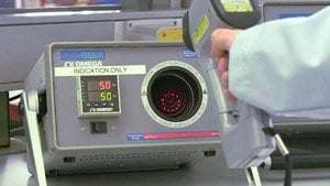 Image Caption Title
Signal Processing Direct Output. Non contact thermometers convert the intercepted thermal radiation into an electrical signal proportional to the spectral radiance emitted from the target surface.
Linearized Output. An electronic network converts the thermal radiance signal into an electrical current/voltage proportional to temperature.
Sample and Hold. The momentary temperature reading, selected by an external trigger is held (frozen) until replaced by a new value in the next sampling cycle.
Maximum Value or Peak Hold. The highest temperature reading over the specific measuring period is displayed. Reset is triggered by an external signal.
Minimum Value or Valley Hold. The lowest temperature reading during a specific measurement period is displayed. Rest is triggered by an external signal.
Peak to Peak. The difference between the maximum and the minimum temperature readings during a specific measurement period is displayed.
Speed of Response. Short response time is needed to follow rapidly changing dynamic temperature processes. Long response time integrates all signal variations during a specific measurement period and enhances temperature resolution in order to average changing values or to improve measurement precision.
Automatic Trigger (Wave Function). The highest temperature reading is detected and displayed. Reset is triggered automatically when the signal reaches an adjustable threshold, but the last peak value is held on display until it is replaced by the following peak value. This technique is appropriate for rapid sampling and analysis of intermittent target values, without the use of external trigger signals.
Alarms. An output signal (relay) is activated when the signal reaches a preset temperature value. Two independent set points – HI/LO – are generally provided.
Accesories for non contact thermometers Water Coolable Jackets. Water cooling extends the sensor’s ambient temperature range up to 400°C (752°F) or beyond.
Air Purge Fittings. Lens barrels or attachments with fittings for compressed air are designed to direct a clean air flow across the lens surface. They keep the optical sight paths free of vapors, fumes, and dust.
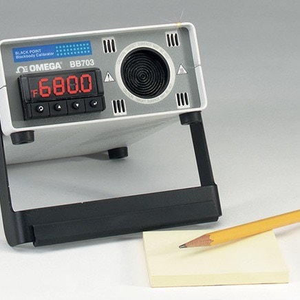
Calibrators for non contact thermometers Deep cavities controlled at a homogeneously distributed temperature serve as blackbody simulators for the calibration of radiation thermometers. To accommodate the variety of instruments, they provide an effective aperture of ~ 1 in. (25 mm) and are optimized for their operating temperature range:
- Stirred water bath: 30-100°C (86-212°F)
- Aluminum core: 50-400°C (122-752°F)
- Stainless steel core: 350-1000°C (662-1832°F )
- Portable, battery operated field calibrator: fixed temperature choices from 40°C-100°C (104-212°F)
On-Line Instruments. These devices are generally used for continuous process monitoring and control. They are available in low- and hightemperature models, each with its own operating specs (see Table 1).
Portable Instruments. Portables are typically favored for process checks, preventive/predictive maintenance, thermal surveys, R&D, and temporary temperature monitoring. The low- and high-temperature versions differ in performance, as shown in Table 2.
