Application
Control cables play a critical role in assuring the safety and operational integrity of a wide variety of mechanical and electromechanical devices, including lawn mowers and bicycles. Product development testing is necessary to ensure that control cables have adequate tensile strength for use in typical operating conditions, and must specify the maximum and minimum loads to which the cables may be subject while in use.
In this application, load testing of the control cable is conducted in a custom-designed environmental chamber using a load cell. Testing can be conducted under low-load conditions as well as with greater axial forces applied to obtain minimum and maximum tolerances for the cable.
Other specific requirements of this application, include the need for the load cell to withstand side and shear loads as well as to tolerate heat conducted through the rod and to retain accuracy at temperatures ranging from approximately 30°F to 90°F. Most load cells can tolerate steady axial forces, but only a few can withstand shear or side loads. Beam load cells are the best choice for use in conditions where non-axial forces may be present, such as in this application.
OMEGA products used in this application


Products
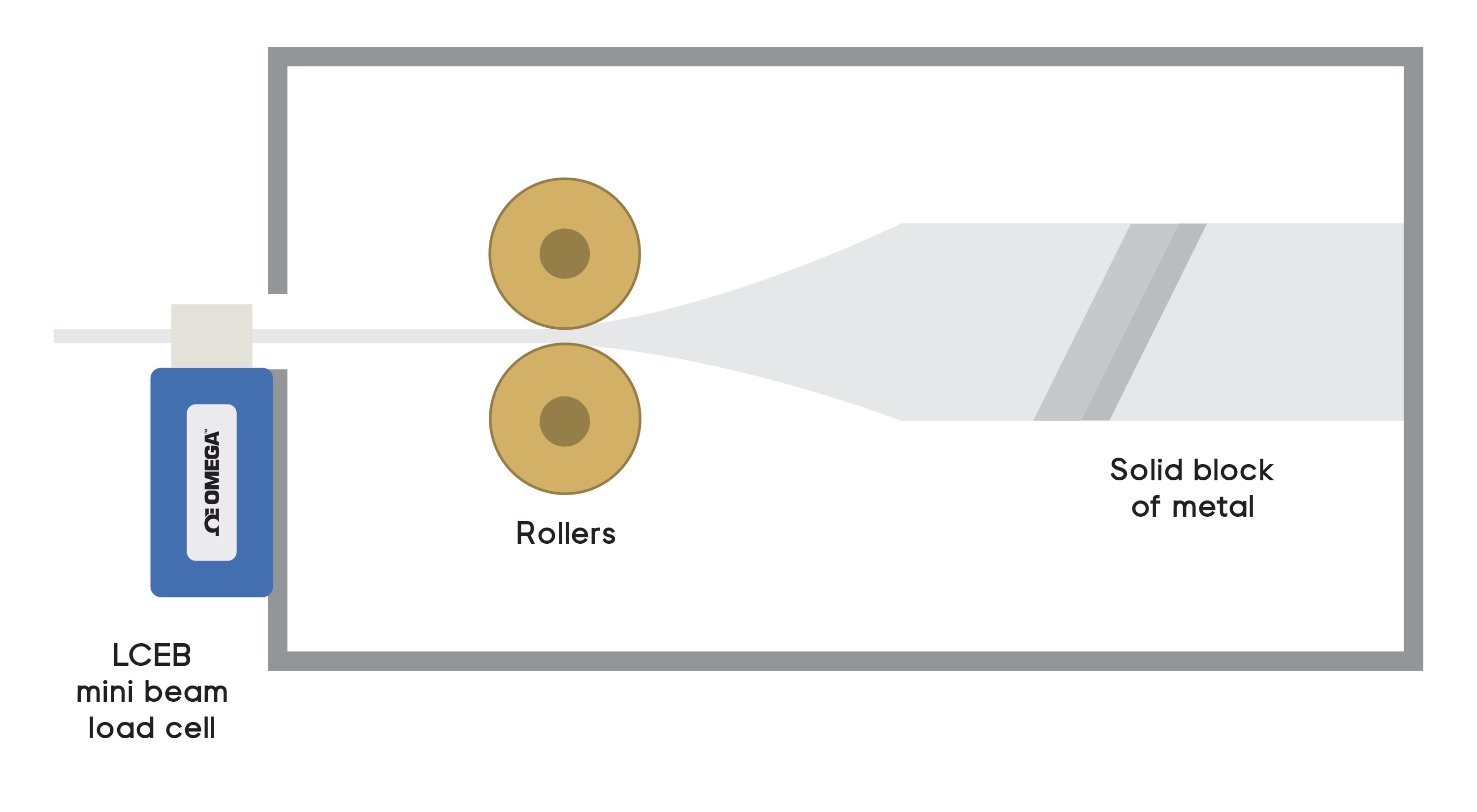
The figure above shows the schematic of the load testing system. The solution includes two OMEGA products:
LCEB-50: This mini-beam load cell offers exceptional accuracy in compression when deployed in controlled environments. It is small in size, has low creep and excellent temperature compensation, and can withstand shear and side loads.
DP400S: A high-speed strain meter designed as an output display for load cells and pressure sensors that includes an isolated power supply and offers a programmable conversion frequency up to 1.2 KHz and resolution up to 24 bits.
How it Works
- Mount the control cable within the environmental chamber such that a section of the cable extends outwards onto the small platform where the load cell is located.
- Compute the accuracy that is required for the testing output.
- Verify that strain meter is calibrated to the appropriate number of decimal places.
- Apply force to the loading surface.
- Measure the stretch force being applied to the cable.
- Display results to the strain meter.
- Read and record results.
Results
The testing system was able to accurately measure the control cable’s performance during the testing procedure. This enables the product tester to verify that the cable conformed to minimum and maximum load tolerance standards.
Pro Tip
When an application requires a load cell with high resolution and accuracy over a wide range of load forces, select a high-accuracy shear beam load cell.